3. Procedure Generation Tool
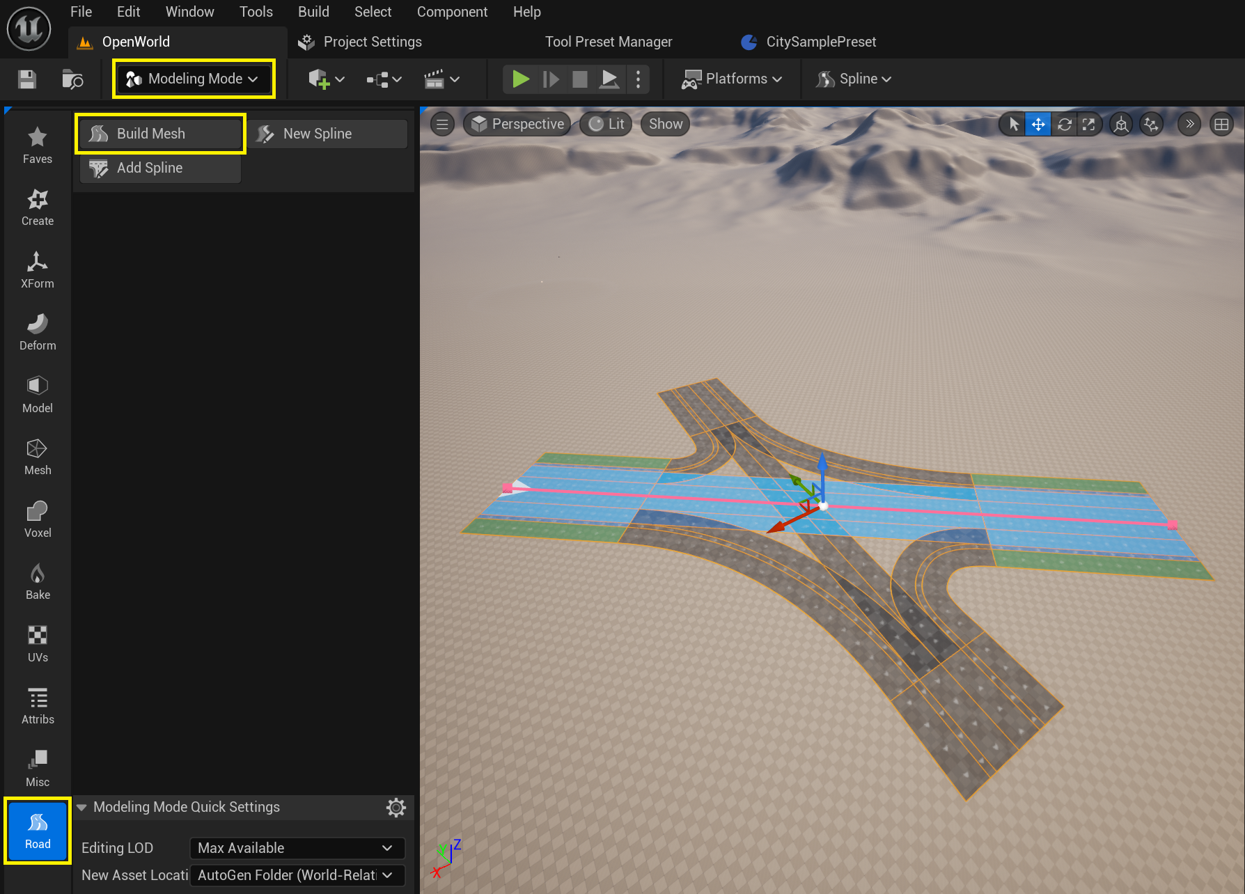
The Procedure Generation Tool converts road layout data stored in URoadSplineComponent into actual 3D assets placed in the level: static meshes for the drive surface, sidewalks, and curbs; spline meshes for road markings; and decals for surface overlays. To access it, switch Editor Mode to Modeling Mode and select the Road toolset.
All URoadSplineComponent instances within a single actor are triangulated together as one unit. This means intersections (whose splines share an actor) are generated as a seamless mesh, while splines in separate actors are generated independently — see Spline grouping rules below.
3.1. Build Mesh Tool
This Modeling Tool allows you to generate assets (static meshes, dynamic meshes, spline meshes, etc.) and create Actors with these assets on the scene.
To use the Build Mesh Tool, simply select one or more actors containing URoadSplineComponent, activate the Build Mesh Tool, and it will immediately display the preliminary result:
To access the Build Mesh Tool, switch Editor Mode to Modeling Mode and select the Road toolset:
After clicking the Accept button for each selected actor, a new actor with the suffix _Gen will be created. For example, for the actor RoadActor11, the actor RoadActor11_Gen will be generated:
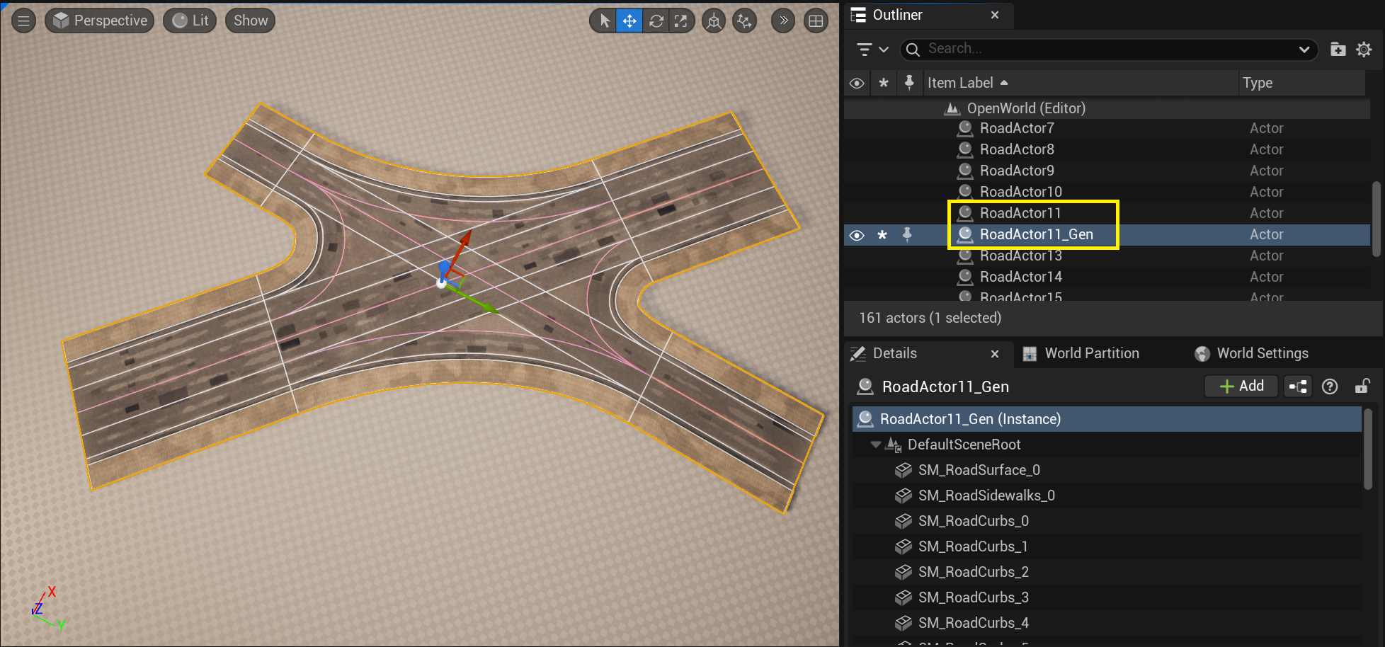
The generated actor contains ActorComponents (usually UStaticMeshComponent, USplineMeshComponent) with references to the generated assets:
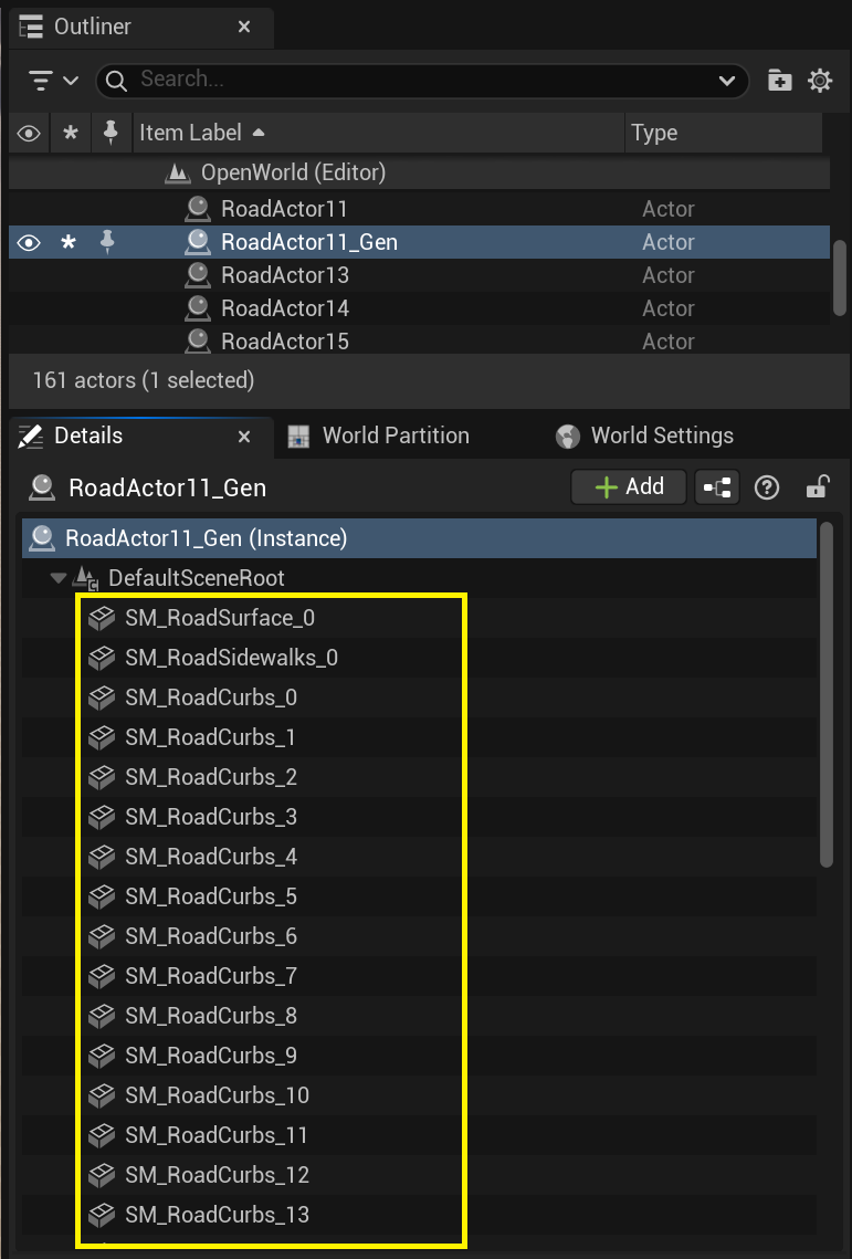
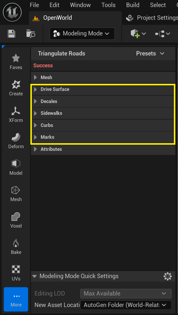
The Build Mesh Tool separately generates assets for:
Drive Surface + Decals
Sidewalks
Curbs
Marks
SplineMeshes
For each of these asset types, there is a corresponding group of parameters in the Build Mesh Tool:
3.1.1. Mesh Lane Materials
All road lanes have a Lane Type:
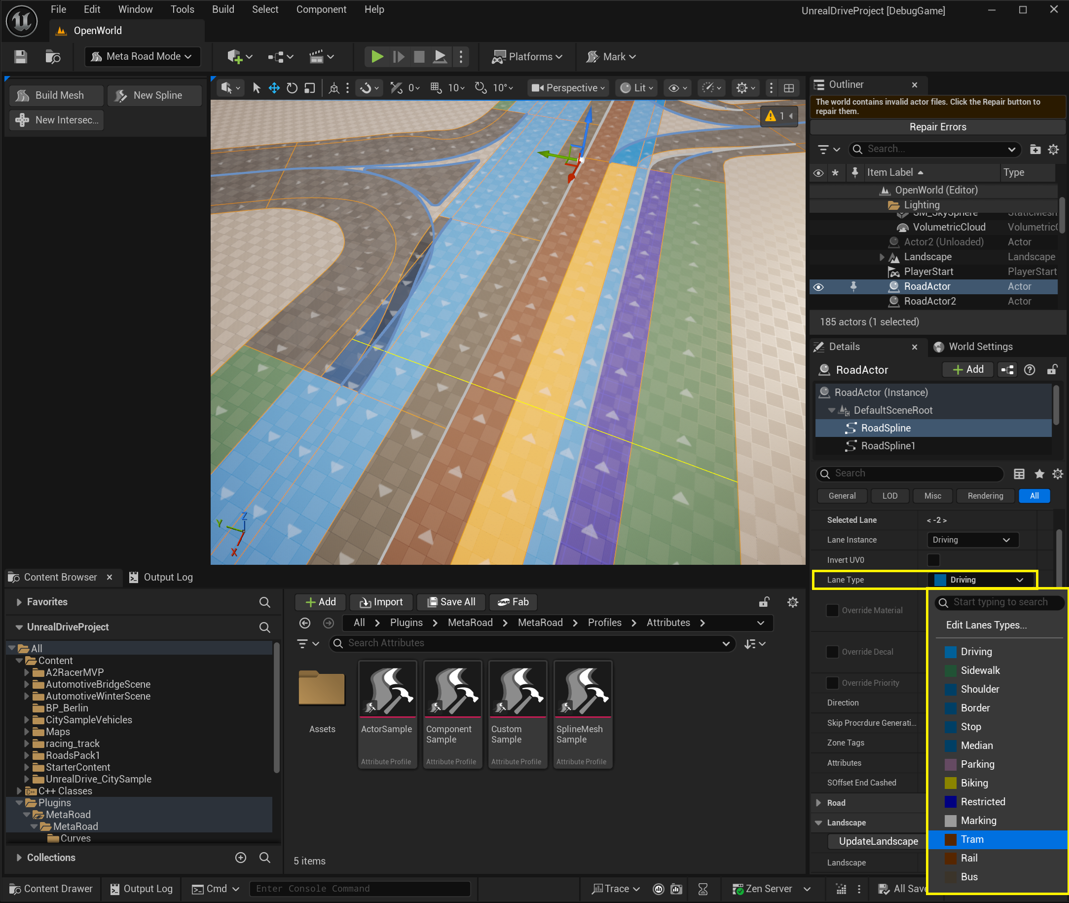
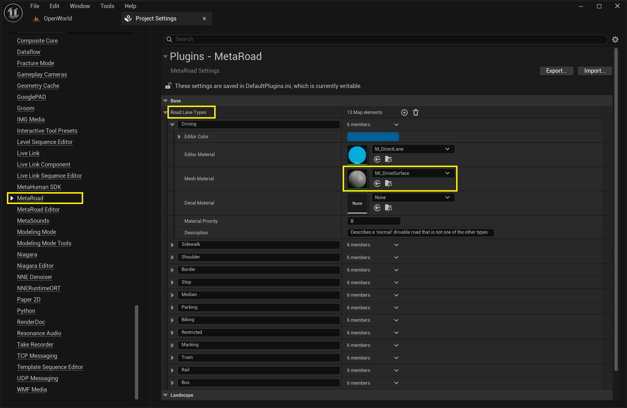
You can add new Lane Type in the Project Settings. Each Lane Type also has a Default Material:
For a selected road lane, you can override the default lane material:
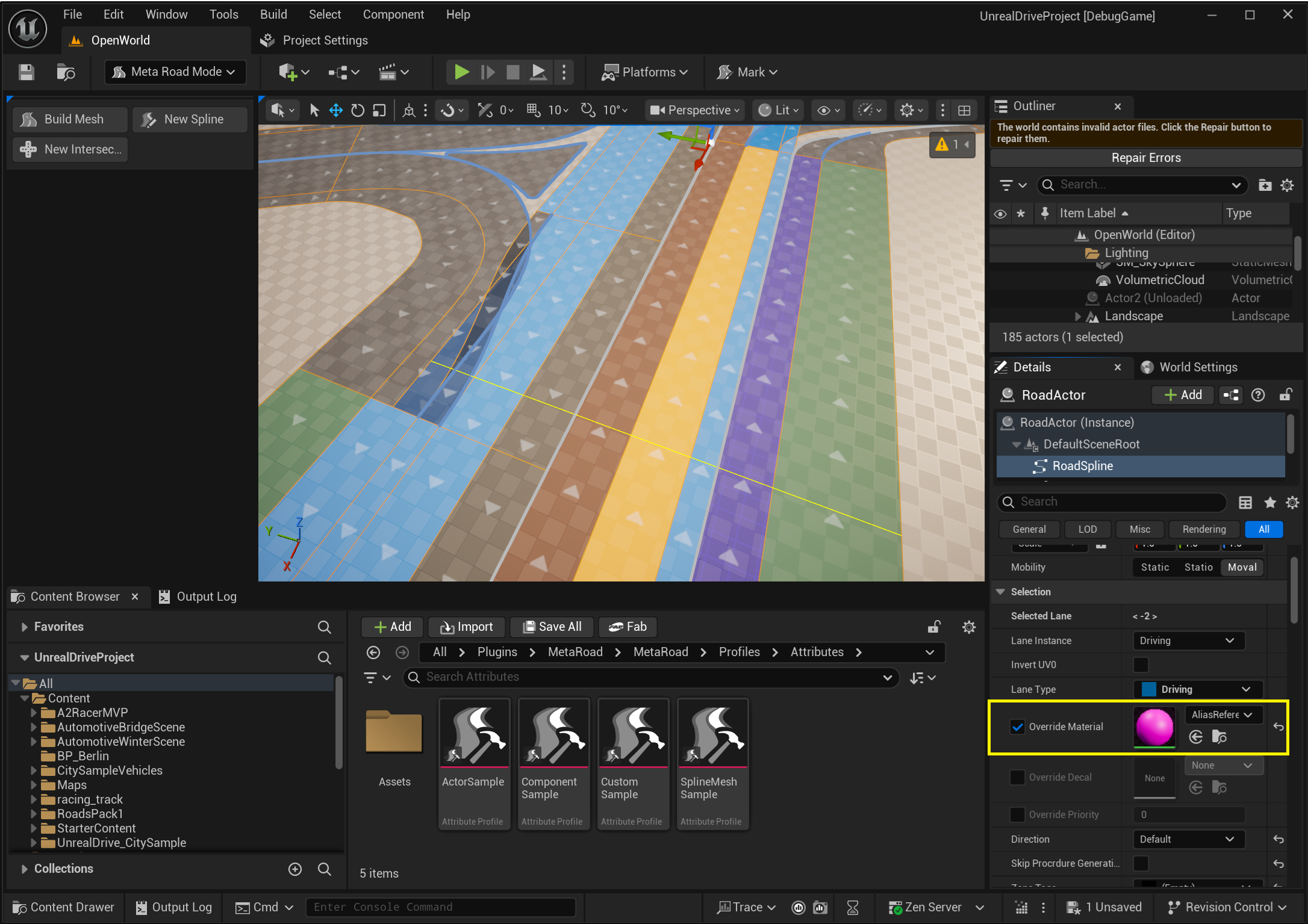
You can also override the default Lane Type material from the Build Mesh Tool settings:
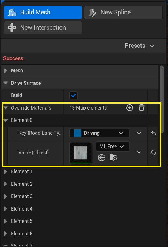
Thus, the priority of determining the road lane material is as follows:
-> Default material from Lane Type description
-> Override materials from the Build Mesh Tool
-> Override materials from the selected road lane menu
3.1.2. Mesh UVs
Procedural generation for Road Surface generates two levels of texture coordinates:
UV0 - a separate track for each lane. UV0 is useful for displaying road ruts or tram tracks.
UV1 - a track for the left and right sides of the road. UV1 is useful for displaying road patches.
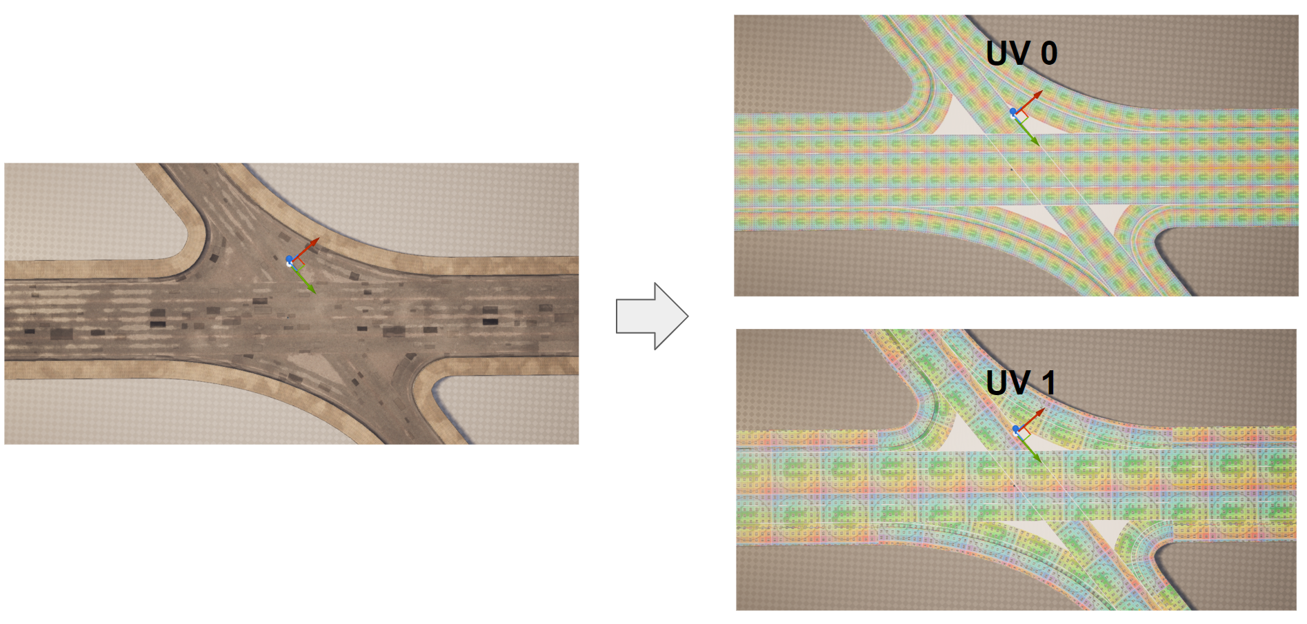
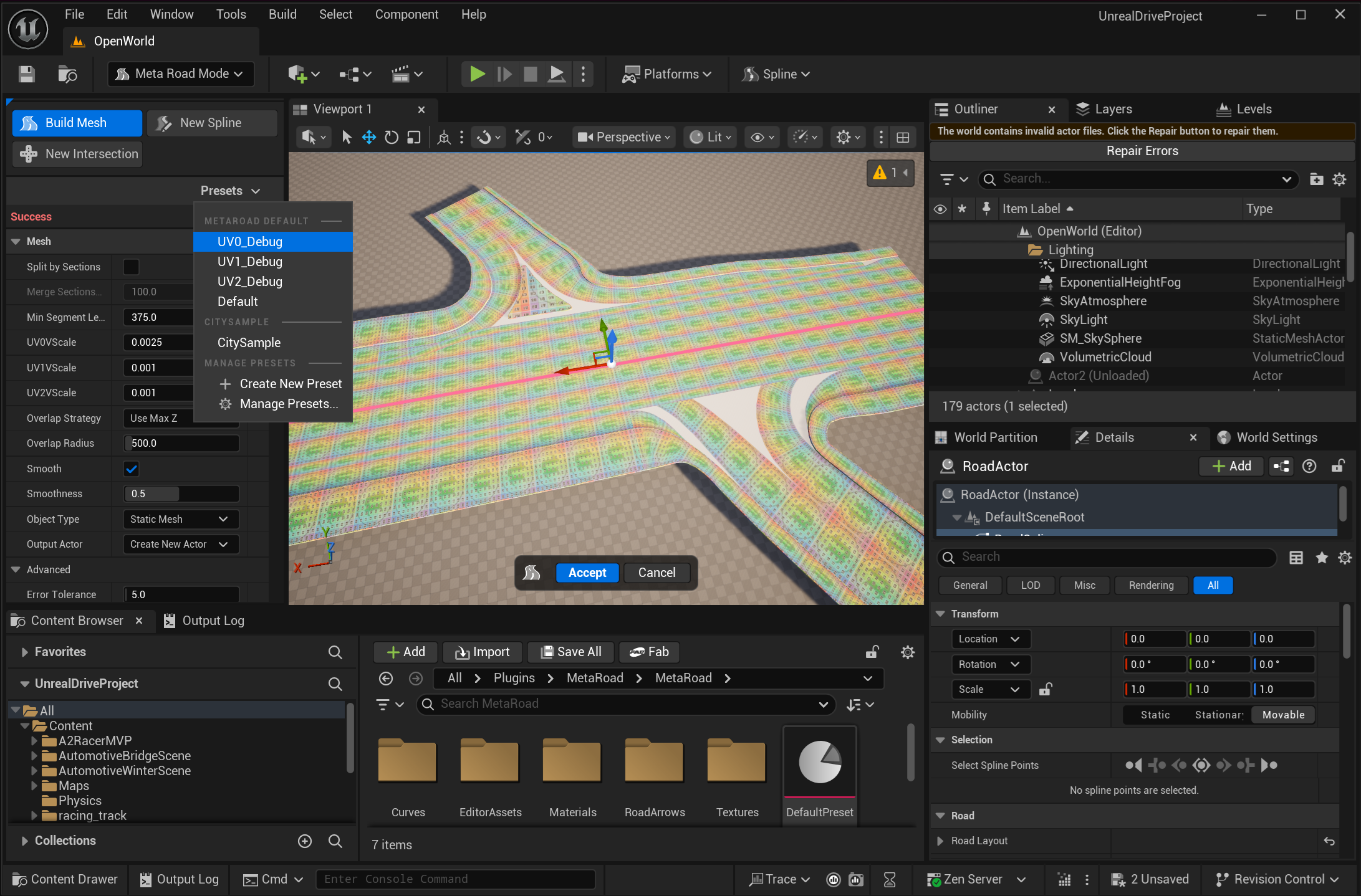
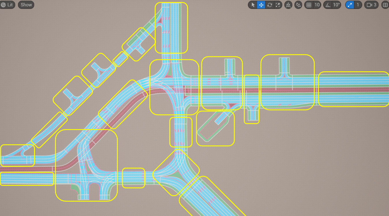
To display debugging materials (as shown in the image above), you need choose UV0 Debug, UV1 Debug or UV0 Debug preset:
3.1.3. Mesh Vertex Color
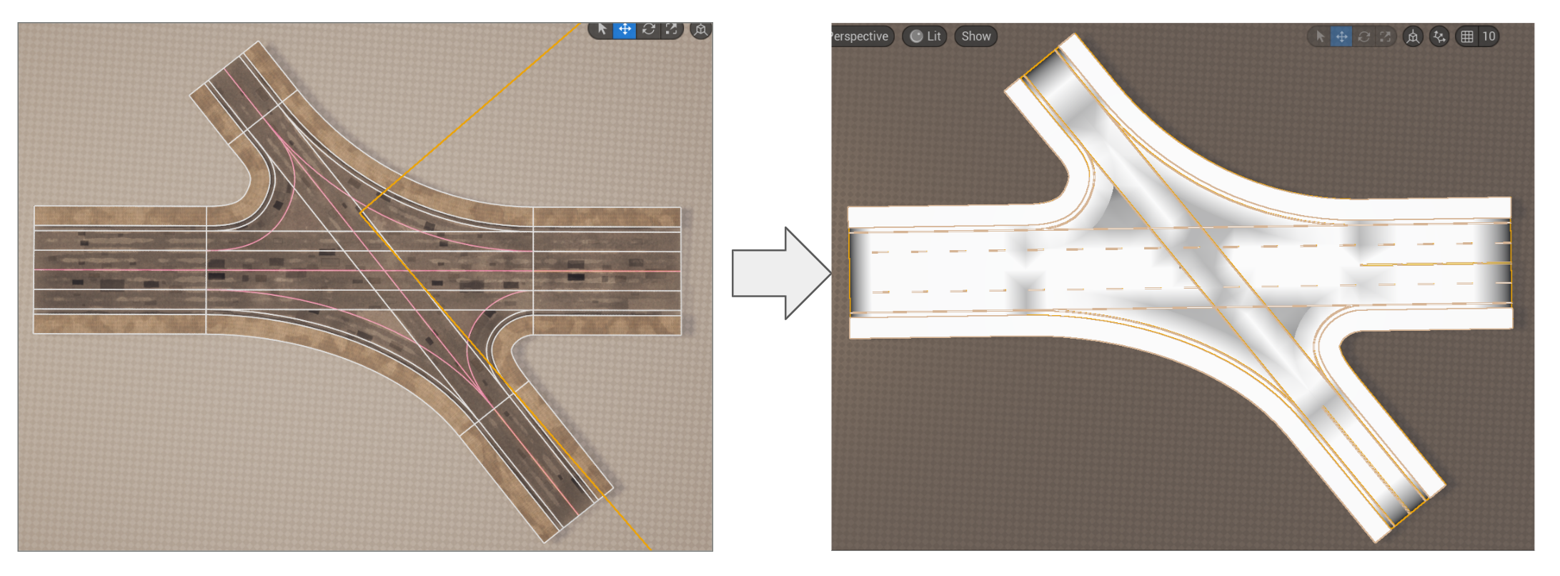
For road surface materials, we recommend using the Vertex Color mesh attribute to designate areas of the mesh where you need to control the presence of textures stretched across the UV0 and UV1 channels (such as puddles, ruts, and patches). This will eliminate artifacts at the seams (areas where several URoadSplineComponent intersect) and improve the overall appearance of the roads:
The following parameters are suggested for parameterizing Vertex Color for Drive Surface:
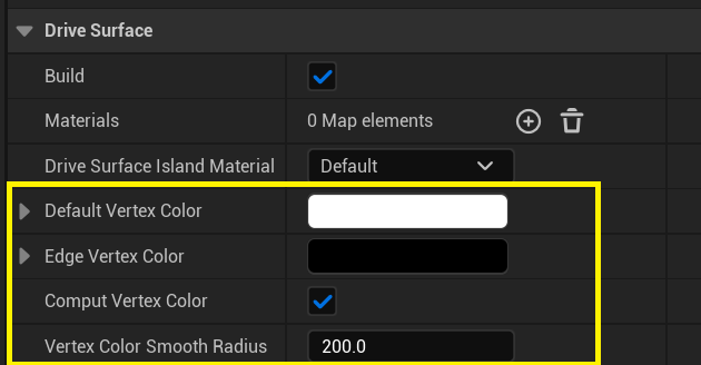
These parameters allow to set the color of vertices in the center and at the edges of the mesh, as well as in the areas where lanes intersect:
However, for complex intersections, you will most likely have to manually “paint” the necessary vertices in Mesh Paintmode, as shown above. In future releases of MetaRoad, it may be possible to improve the vertex color generation mechanism so that you don’t have to resort to Mesh Paint mode.
3.1.4. The principle of spline grouping
Important
It is important to remember that procedural road generation treats each actor containing at least one URoadSplineComponent as a separate generation unit, unrelated to other actors and URoadSplineComponent on the scene. This leads to two rules:
A group of URoadSplineComponents representing an intersection or junction must be located within a single AActor.
Do not place too large sections of the road network in a single actor, otherwise large static meshes will be generated, and UnrealEngine will not work efficiently in terms of rendering and physics optimization.
Examples:
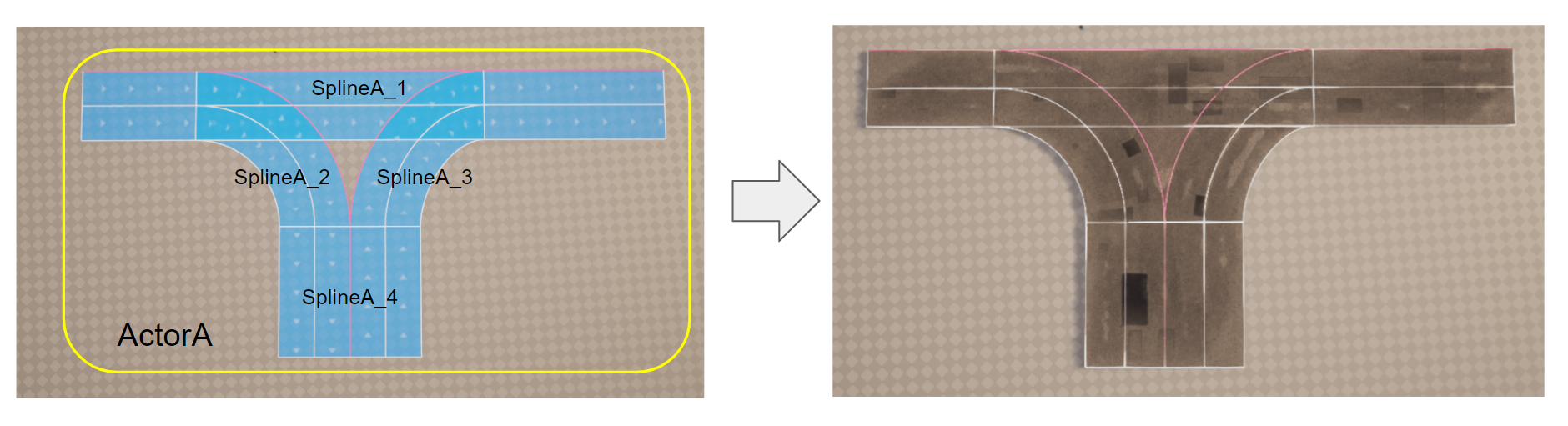
In this example, four URoadSplineComponent (SplineA_1, SplineA_2, SplineA_3, SplineA_4) are located in one actor (ActorA), and accordingly, procedural generation for ActorA will take all four splines into account and correctly generate the intersection.
In this example, there are already two actors (ActorA and ActorB), each containing two components (SplineA_1, SplineA_2, SplineB_1, SplineB_2):
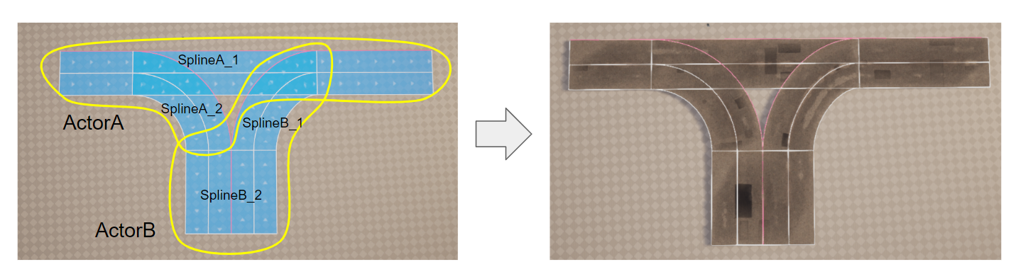
This happens because splines SplineA_1 + SplineA_2 and SplineB_1 + SplineB_2 are triangulated separately, resulting in the following outcome:
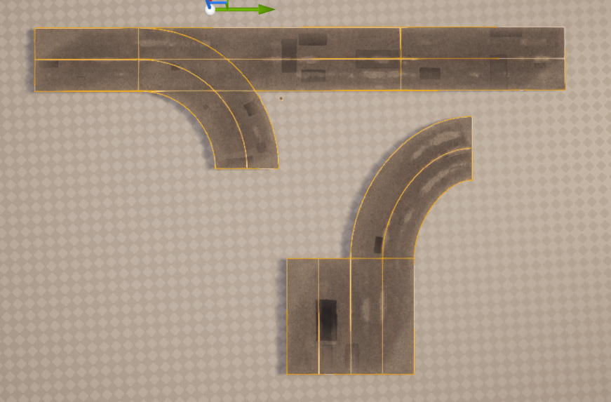
The following example shows how to divide the road network into actors, based on the principle that each intersection/junction is placed in a separate actor:
That is why, for convenience, two modes for drawing splines have been introduced: New Spline and Add Spline (see Draw Modeling Tools). This allows to either add a new spline to an actor or create a new actor with a spline inside it.