Road Model
Basic concepts
The ActorComponent URoadSplineComponent forms the basis of the roads, roads network model and the entire MetaRoad plugin.
URoadSplineComponent is the only component needed to represent a road network graph. Although the component itself describes only a single simple road segment, a combination of URoadSplineComponent can describe even very complex road networks, interchanges, and intersections.
Any section of the road network on the scene is an arbitrary AActor that includes one or more URoadSplineComponent, with one road typically consisting of one URoadSplineComponent and intersections or junctions consisting of several.
Those familiar with the ASAM OpenDrive specification will find all the ideas implemented in URoadSplineComponent very familiar.
Indeed, MetaRoad has emphasized much of this specification.
You author every part of this model inside the Meta Road editor mode, using one Edit sub-mode per aspect of the road (Spline / Section / Offset / Width / Attribute). Each section below links to the sub-mode that edits it — see The Meta Road Editor Mode for the overview.
Road Reference Line
URoadSplineComponent - inherits from USplineComponent, i.e. it has all the properties of the base spline, which is the reference line along which the road is generated.
The reference line is marked in pink. It is a left-handed coordinate system. The S-axis (or S-Offset in UI) follows the tangent of the road reference line. The R-axis (R-Offset in UI) is orthogonal to the S-axis and may be rotated around the S-axis by superelevation. The left-handed coordinate system is completed by defining the up-direction H orthogonal to S-axis and R-axis.
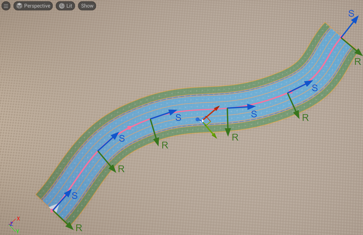
Edit the reference line — its points, tangents and arc nodes — in Spline Mode.
Road Lanes
Lanes are an essential part of all roads. Lanes are attached to the road reference line of the road and are defined from inside to outside. A minimum road definition requires a center lane and an additional lane with a defined width. The number of lanes per road is not limited.
The center lane has no width and serves as reference for lane numbering. The center lane itself has the lane index 0. The numbering of the other lanes starts at the center lane: Lane numbers descend to the right, meaning a positive R-direction, and ascend to the left, meaning a negative R-direction.

This figure shows the center lane for a road with multiple traffic lanes and different driving directions. In this case, the center lane separates the driving directions, depending on left- and right-hand traffic, specified in Road type. Because no lane offset is used, the center lane is identical to the road reference line.
Add and configure lanes in Section Mode; edit each lane’s width curve along the road in Width Mode.
Zone Types
A Zone Type defines the surface of a lane or polygon (driving, sidewalk, shoulder, marking, …) — its material, decal, priority and color. Types are registered project-wide in Project Settings → Plugins → Meta Road → Road Zone Types (built-in + user-defined); a lane or closed-loop fill then uses a Road Zone — a Zone Type plus optional overrides. Full details: Road Zones and Zone Types.

Assign a lane’s Road Zone and Zone Type in Section Mode.
Lane Direction
Each road lane has a direction. On the graphs, this direction is shown by white moving arrows. This direction is specified by a combination of different elements and attributes. For any individual lane, you can change the direction of movement.
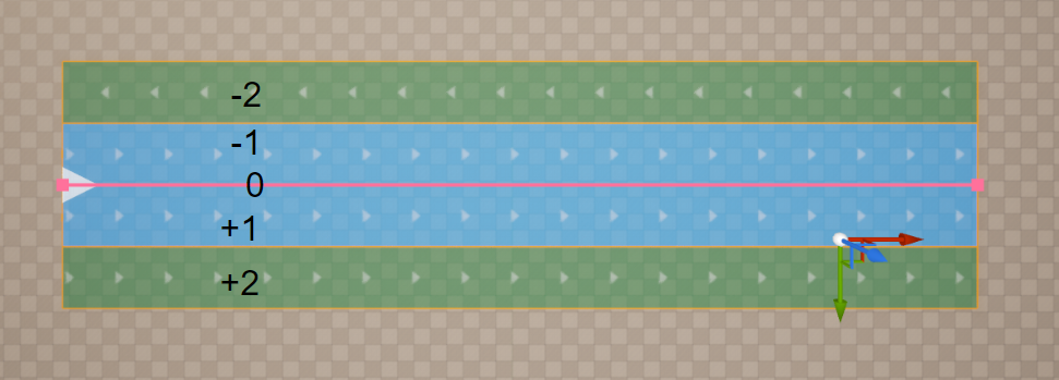
This figure shows that the line with index -1 has an inverted direction.
Flip a lane’s direction in Section Mode (Reverse Direction).
Lane Groups
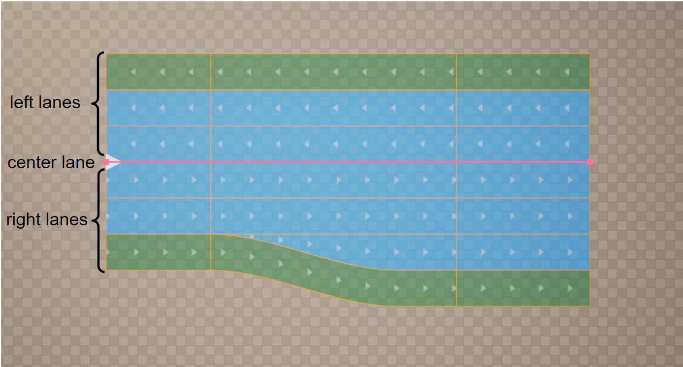
For easier navigation through road description, the lanes within a lane section are grouped into left, center, and right lanes.
Lane Sections
Lanes may be split into multiple lane sections. Each lane section contains a fixed number of lanes.
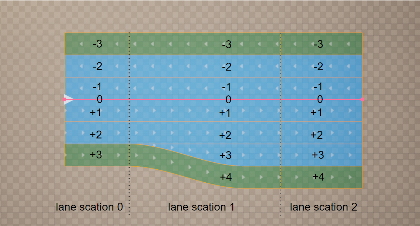
This figure shows that every time the number of lanes changes, a new lane section is required. Lane sections are defined in ascending order along the road reference line.
Split and remove lane sections in Section Mode.
Asymmetric Lane Sections

This figure shows how lane sections for complex roads may be defined for one side of the road only - left, right and both sides
In these cases the left and right sides of a road need section boundaries at different positions along the reference line — for example, when a right-turn lane starts at S=500 m while the left side remains unchanged. This is called an asymmetric layout.
Create one-sided (asymmetric) splits with a section’s Side in Section Mode.
Lane Offset
A lane offset may be used to shift the center lane away from the road reference line. This makes it easier to model local lateral shifts of lanes on roads, for example for left turn lanes.
A combination of lane offset and shape definition can lead to inconsistencies depending on the interpolation used for the lane offset. Because linear interpolation is used for the road shape along the road reference line, linear interpolation should also be used for the offset definition to enable consistent combined use of both definitions.
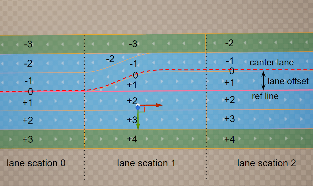
This figure shows the offset of the center lane away from the road reference line.
Edit the offset curve in Offset Mode.
Lane Attributes
Lane attributes are typed metadata sampled along a Road Lane by arc-length (SOffset). A single lane can carry
many attributes at once, and they are the plugin’s primary extensibility layer — used for road markings, speed
limits, traffic priorities, geometry generated along the lane (fences, guardrails, vegetation), landscape deformation,
and arbitrary custom data. Full data model and the catalog of available types: Attributes.
To add and edit them in the editor, see Attribute Mode.
See also
Attributes — the attribute data model, keys, and the catalog of types.
Intersections and Junctions — how roads link into intersections (the connection graph).
Closed-Loop Splines — islands, crossings and arrow fills.
Road Zones and Zone Types — lane surface types and their materials.